Selected work
Stabilising a high-voltage power operational amplifier
Tuning a PA78DK output stage for short high-voltage pulses. Analogue compensation changes were combined with firmware limits on the rate of voltage change, set separately for rising and falling edges.
Anonymised professional project · my role: power-stage diagnostics and stabilisation
- Application
- Laboratory instrumentation
- Amplifier
- Apex PA78DK
- Pulses
- typically shorter than 100 µs
- Focus
- stability, slew rate and compensation
Assignment and context
A board with a PA78DK power operational amplifier served as the output stage for arbitrary-shaped pulses, typically shorter than 100 µs. The rate of output-voltage change (slew rate) was important, typically around 60 V/µs in this application.
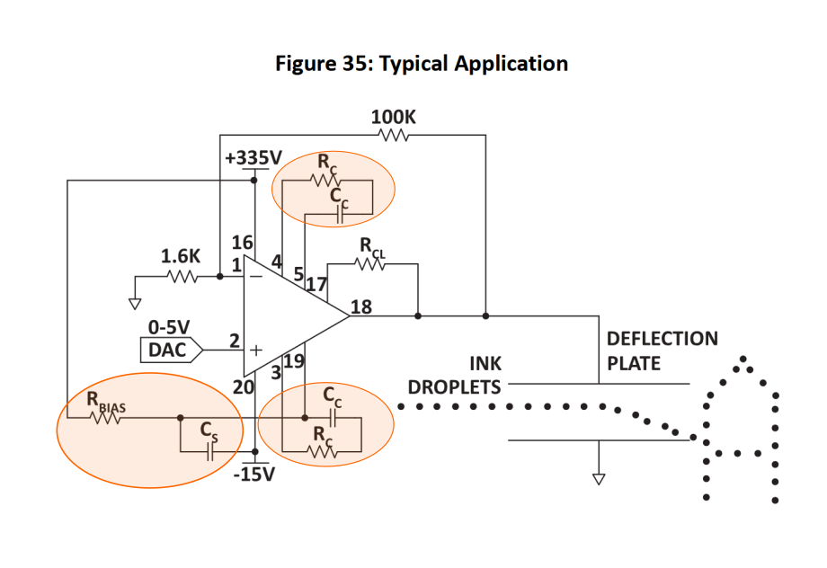
Fast voltage transitions produced instability, and rising and falling edges behaved differently. This difference also relates to the characteristics of the PA78 itself: its datasheet specifically addresses falling-edge oscillations and prescribes an external capacitor to suppress them.
Approach and solution
My task was to investigate the instability and tune both the analogue stage and MCU control. The objective was to retain fast edges within the range where the output remained stable.
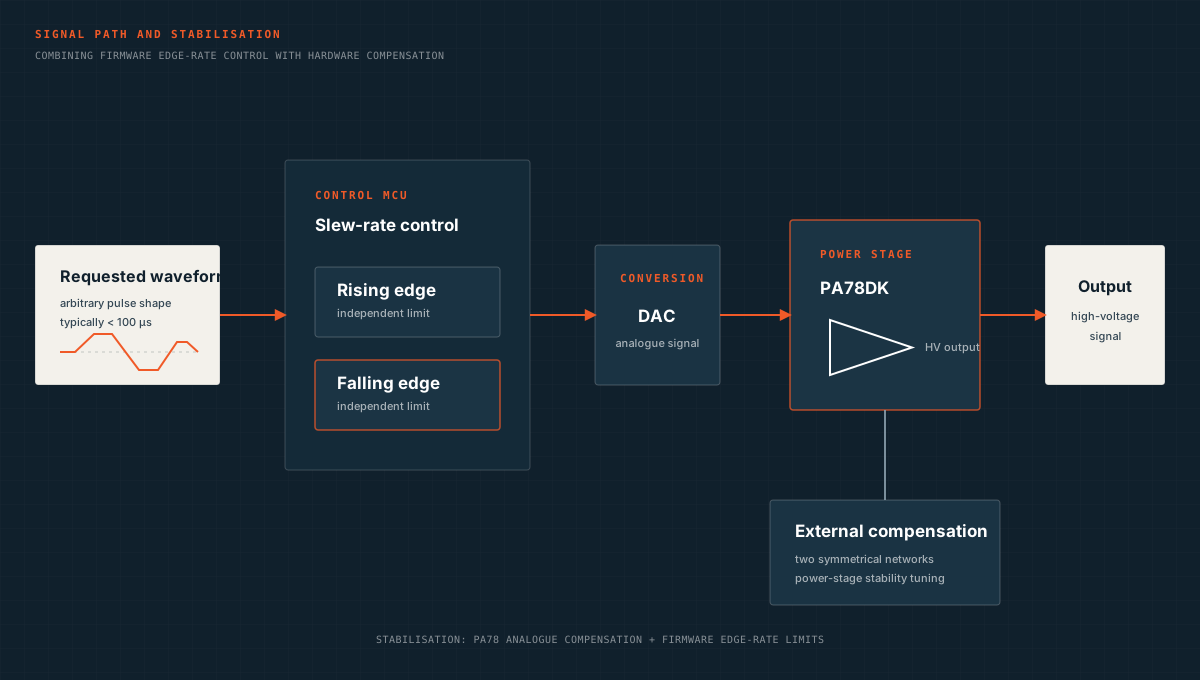
- Compensation networksCompensation networks were already present on the board, but one connection did not follow the manufacturer’s recommendation. I corrected it and tuned the analogue compensation according to the PA78 documentation, which calls for two symmetric compensation networks.
- Edge asymmetryTuning showed that the rising edge allowed a higher rate of voltage change, while the falling edge required a lower limit. The application settings therefore accounted for the amplifier’s different behaviour on each edge.
- Slew-rate controlI implemented a slew-rate limiting algorithm in the MCU firmware controlling the DAC, with independent limits for rising and falling edges. This allowed the analogue compensation to support a faster rising edge while the software limited the falling edge.
Result
The combination of compensation changes and software edge-rate limits stabilised the output stage. The rising edge could use a higher slew rate while the falling edge was limited separately.